 线束工程师服务平台
可以搜到:产品、技术、资料、新闻、检测、企业、视频
- 全国客服热线
- 17135242547
- 在线交谈
 线束工程师服务平台
可以搜到:产品、技术、资料、新闻、检测、企业、视频
电动汽车 (EV) 电缆线束是当今电线加工领域最热门的话题之一。这是一个非常新且令人兴奋的市场,随着新技术的出现,它正在迅速变化。对于那些希望扩展到这个市场的人来说,了解有效自动化高压 (HV) 电缆连接器组件的过程非常重要。
EV 应用中使用的高压连接器有许多组件,因此必须按特定顺序执行多个工艺步骤。虽然大多数客户希望自动化每个流程步骤,但往往无法证明全自动系统的成本是合理的。
一些工艺步骤更具挑战性,需要更高的精度。例如,去除箔层或切割屏蔽层更为关键,因为连接器的性能或安全性可能会受到显着影响。此外,几乎所有连接器和电缆类型都需要一些工艺步骤,仅某些特定的连接器需要其他工艺步骤。根据特定连接器系列的数量,仅关键或常见步骤与通过人工操作继续执行更简单或不常见的步骤,自动化可能更有意义。但是,如果数量证明它是合理的,它都可以自动化。
目前,超过 97% 的高压应用需要屏蔽电缆,无论是多芯电缆还是同轴电缆。HV 应用范围从 3mm2到 120mm2的单芯(同轴)或 2×2.5mm2到 5×6.0mm2的多芯电缆,用于种类繁多的单电缆和多电缆连接器。因此,认真考虑将其产品扩展到 HV 电缆组件的客户必须着眼于不仅提供高精度而且具有完全灵活性的自动化解决方案,以便在知道未来处理要求可能会发生变化的情况下保护任何投资。重要的是,系统可以在现场扩展,以便它们可以随着您的业务发展和适应。
由于其不同的功能和/或结构,不同的连接器通常具有非常不同的单独工艺步骤。但是,有一些基本步骤适用于几乎所有这些步骤,这些步骤与正确剥开电缆和加载套圈有关。
1) 去除外套和箔
屏蔽层周围没有箔层的电缆自然更容易和更快地剥离。这些电缆可以使用圆角固定刀片、旋转剥线刀片或激光剥线器进行剥线。
Radius 固定刀片可能是最快的,但可能不是最安全的质量。如果一个刀片比另一个更锋利,刀片将无法均匀地穿透绝缘层,并可能损坏屏蔽层。如果电缆不是很同心,几乎不可能不损坏屏蔽层。最后,更改为不同的电缆尺寸也需要更改刀片尺寸。
激光剥离很受欢迎,因为激光束会从护罩反射出来,因此无法损坏护罩。但是,如果屏蔽层编织不严密,激光可以穿透屏蔽层并损坏内层。激光剥离器需要抽烟,因为有些烟雾是有毒的。与其他剥离方法相比,它们也是最昂贵的。
旋转剥离将使用刀片和导体检测系统提供最干净的切割,可防止损坏屏蔽层。非同心电缆可采用特殊工艺。
当外护套模制到护罩中时,更难在不干扰护罩的情况下移除护套。在这些情况下,在将嵌块拉离电缆的同时沿特定方向操作嵌块有助于嵌块脱离屏蔽层。
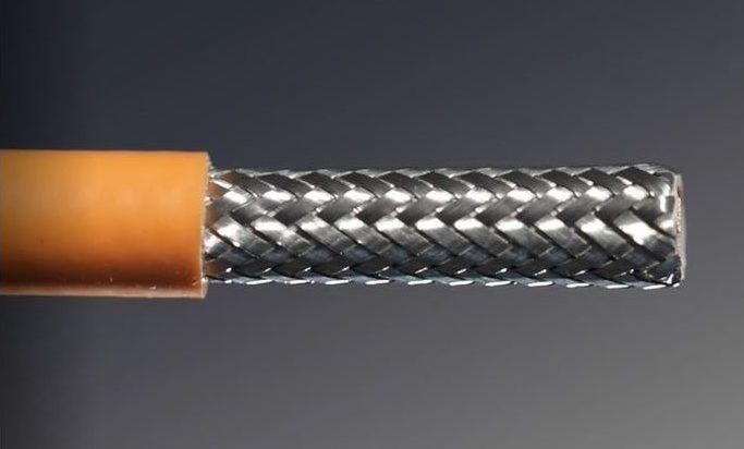
加工高压电缆如果电缆有箔层,则必须将其剥离干净,与外护套齐平,不得留下任何标志。这对于固定刀片几乎是不可能的。除非将箔片粘合到外护套上,否则使用激光系统当然是可能的。激光系统需要空间让激光到达箔片。但是,如果将箔片粘合到外护套上,则任何拉动小块都可能导致箔片撕裂不均匀。此外,激光不会切割箔重叠的地方。
使用旋转剥离刀片,可以在不拉动块的情况下对箔进行刻划。可以通过操纵电缆并在移除时扭动护套块来同时移除护套块和箔。结果是干净的铝箔切割与外护套齐平。
2) 组装内套圈
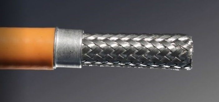
将套圈加载到电缆上很关键,但如果手动完成,则不会太具有挑战性。然而,如前所述,不同的连接器使用不同的套圈。因此,应该可以使用一些特定于电缆和套圈的部件更换不同的套圈。系统还应该能够检测套圈是否正确类型以及它是否在电缆上正确定向。
将套圈安装到电缆上是一个可以手动完成的步骤,以节省成本,因为自动加载系统非常昂贵。
3) 切割/移除屏蔽
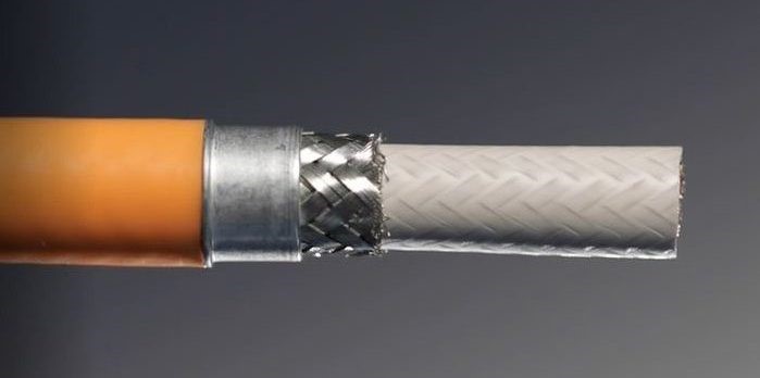
屏蔽高压电缆对于高压电缆,使用传统的旋转剥线装置正确切割屏蔽层非常具有挑战性,特别是如果电缆具有非同心层或不圆的情况。电介质和填料的完整性对于电缆的正常性能至关重要,传统的旋转剥线机有损坏内层的风险。铁砧和冲压系统可确保内层不会损坏,并围绕电缆 360° 清洁、均匀地切割屏蔽层。
最终的屏蔽长度将取决于所使用的套圈,因为它会缠绕在套圈上。切割必须干净且一致,否则长线可能会导致其他组件短路,而短线可能会降低套圈压接的完整性。
有时屏蔽长度比电介质的长度长。这些应用要求屏蔽在修剪后打开并折回,以便剥离内层。
4) 折叠屏蔽
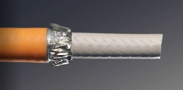
防护罩会折回到套圈上,但在某些情况下,不会完全折回。不同的连接器需要不同的折叠角度以确保连接器正确装配在一起。折叠角度可以在 90° 到 180° 之间,但折叠必须均匀,围绕套圈 360°。屏蔽绞线末端必须在规定的公差范围内,以确保适当的性能。太粗的股线可能会导致短路,而当外部套圈卷曲时,短股线可能无法正确固定屏蔽。
5) 去除电介质/填料
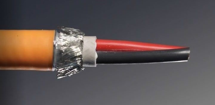
电介质或填料可以以与外护套相同的方式去除。多芯电缆不允许对导体绝缘有任何损坏。
对于同轴电缆,导体检测可以起到很大的作用,以确保中心导体不会被剥线刀片损坏。与外护套一样,系统必须能够容纳非同心电缆,以提供最大的灵活性。
6) 多导体定向和剥离
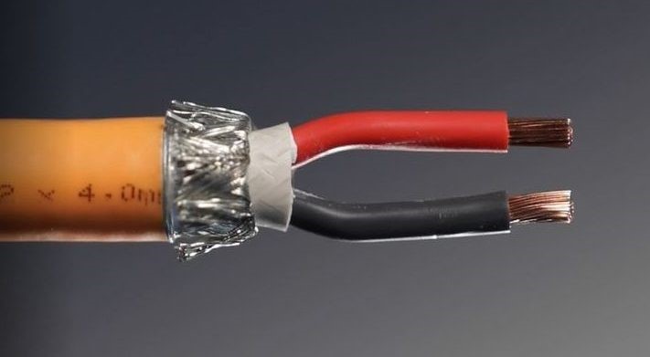
在端接多芯电缆之前,必须正确定向电缆,以便在将导体插入连接器时极性正确。复杂的系统必须能够识别电线颜色,然后相应地旋转电缆而不会丢失电缆位置。
一旦正确定向,就可以根据连接器腔间距形成导体以实现端接。正确形成导体后,应在具有导体检测功能的设备上剥去末端,以确保线股不受损坏。
7) 终止
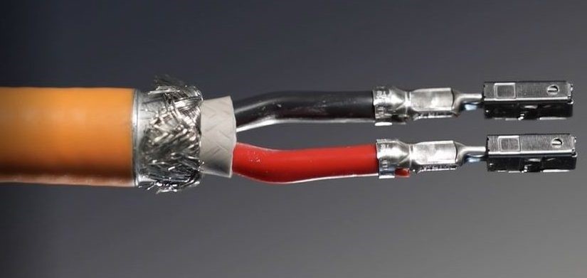
内导体压接或超声波焊接到端子上。自动化系统可以将合适的压接机与压接力监控系统集成在一起。超声波焊接系统通常具有集成监控功能,以确保正确焊接。
可以集成3个自动化系统研发方系统是非常方便的。这些系统可以最大限度地减少已经经历过冗长批准过程的压力机和焊接系统的验证过程。
8) 多导体连接器加载
对于将要端接并装入连接器的多芯电缆,电线末端和端子位置必须非常一致,这一点至关重要。这将确保端子将正确加载并锁定到连接器中。
如果体积合适,后续的外壳或组件可以自动应用并锁定到位。但是,上面列出的步骤 1 到 4 和 6 是最广泛应用的最常见的工艺步骤。自动化这些流程步骤可能会给您带来最好的投资回报,因为它们是最常用的。这些步骤对于确保适当的连接器性能也是最关键的。
新的视觉检测系统可以 360° 检测电缆周围。人工智能用于识别电缆组件的不同层以进行彻底分析。可以为每个组件编程许多质量特性。
在询问自动高压电缆连接系统时,请准备好以下有关您要运行的所有应用程序的信息:
电缆规格和剥线要求
连接器规格和必要的工艺步骤
质量保证要求
生产要求和/或所需的周期时间
有了这些信息,自动化供应商将能够为您的生产要求以及预期性能提供最具成本效益的系统的建议,无论是半自动还是全自动系统。
考虑到 EV 技术的发展速度,自动化系统应该在现场、在您的设施中具有灵活性和适应性,而不会造成生产的重大中断。例如,应该可以将半自动站移动到全自动平台上。同样,随着时间的推移,随着交易量的增加,全自动平台应该是可扩展的。此功能将为您提供最大的灵活性,并使您能够继续利用您的投资。
英文版如下:
Electric Vehicle (EV) cable harnesses is one of the hottest topics in the world of wire processing today. It’s a very new and exciting market that is changing rapidly as new techologies emerge. For those looking to expand into this market, it is important to understand the process of effectively automating high voltage (HV) cable connector assemblies.
High voltage connectors used in EV applications have many components, therefore there are several process steps that must be performed in a specific sequence. While most customers want to automate every process step, often times the cost of a fully automatic system cannot be justified.
Some process steps are more challenging and require more precision. For instance, removing the foil layer or cutting the shield is more critical because connector performance or safety may be affected significantly. Furthermore, some process steps are required for almost all connectors and cable types whereas other process steps are required only for certain connectors. Depending on the volume of a particular connector series, it might make more sense to automate only the critical or common steps and continue the simpler or uncommon steps with manual processes. However, it can all be automated if the volumes justify it.
Currently more than 97% of HV applications require shielded cables, whether they be multi-conductor or coaxial cables. HV applications range from 3mm2 up to 120mm2 in single-conductor (coaxial) or 2×2.5mm2 up to 5×6.0 mm2 in multi-conductor cables for a tremendous variety of single- and multi-cable connectors. Therefore, customers who are serious about expanding their offering into HV cable assemblies must look at automation solutions that provide not only high precision but complete flexibility so that any investments are protected knowing that processing requirements can change in the future. It is important that systems can be expanded in the field so they can grow and adapt with your business.
Different connectors often have very different individual process steps because of their different functions and/or constructions. However, there are some basic steps that apply to almost all of them and these steps pertain to properly stripping the cable and loading the ferrules.
1) Remove outer jacket & foil
Cables without a foil layer around the shield are naturally easier and faster to strip. These cables can be stripped with radiused fixed blades, rotary stripping blades, or a laser stripper.
Radiused fixed blades will likely be the fastest but perhaps not the safest for quality. If one blade is sharper than the other, the blades will not penetrate the insulation evenly and may damage the shield. If the cable is not very concentric, it is nearly impossible not to damage the shield. Finally, changing to a different cable size requires a blade size change as well.
Laser stripping is popular since there is no way to damage the shield because the laser beam is reflected off of the shield. However, if the shield is not woven tightly, the laser can penetrate the shield and damage the inner layers. Laser strippers require fume extraction since some fumes are toxic. They are also the most expensive, compared to other stripping methods.
Rotary stripping will provide the cleanest cut using blades and conductor detection systems that can prevent damage to the shield. Special processes can be used for non-concentric cables.
When the outer jacket is molded into the shield, it makes it more difficult to remove the jacket without disturbing the shield. For these cases, manipulating the slug in certain directions while pulling it off of the cable helps the slug break away from the shield.

If the cable has a foil layer, it must be stripped cleanly, flush with the outer jacket with no flags remaining. This is nearly impossible with fixed blades. It is certainly possible with a laser system unless the foil is bonded to the outer jacket. Laser systems require space for the laser to get to the foil. However, if the foil is bonded to the outer jacket, any pulling of the slug may cause the foil to tear unevenly. Furthermore, lasers will not cut where the foil overlaps.
With rotary stripping blades, it is possible to score the foil without pulling the slug. The jacket slug and foil can be removed simultaneously by manipulating the cable and twisting the slug as it is removed. The result is a clean foil cut that is flush with the outer jacket.
2) Assembling the inner ferrule

Loading the ferrule onto the cable is critical but not overly challenging if done manually. However, as mentioned, different connectors use different ferrules. Therefore, it should be possible to change over to different ferrules with a few cable- and ferrule-specific parts. The system should also have the ability to detect if the ferrule is the correct type and if it is properly oriented on the cable.
Installing the ferrule onto the cable is a step that could be done manually to save costs since automatic loading systems are quite expensive.
3) Cutting/removal of the shield

Properly cutting the shield consistently with a traditional rotary stripping unit is very challenging for HV cables especially if the cable has nonconcentric layers or is otherwise out-of-round. The integrity of the dielectric and filler are critical for proper performance of the cable and traditional rotary stripping machines risk damaging the inner layers. An anvil and punch system guarantees the inner layers will not be damaged and cuts the shield cleanly and evenly, 360° around the cable.
The resulting shield length will depend upon the ferrule being used since it will be wrapped around it. The cut must be clean and consistent, otherwise long strands may cause shorts with other components and short strands may degrade the integrity of the ferrule crimp.
Sometimes the shield length is longer than the length of the dielectric. These applications require that the shield is opened and folded back after it is trimmed so that the inner layers can be stripped.
4) Fold shield

The shield gets folded back over the ferrule but in some cases, not completely. Different connectors require different fold angles to ensure the connector fits together properly. The fold angle may be between 90° to 180° but the fold must be even, 360° around the ferrule. The shield strand ends must fall within the specified tolerances to ensure proper performance. Strands that are too may cause shorts and short strands might not secure the shield properly when the outer ferrule is crimped.
5) Removing dielectric/filler

The dielectric or filler can be removed in the same way as the outer jacket. Multi-conductor cables are not allowed to have any damage to the conductor insulation.
For coaxial cables, conductor detection can play a big role to ensure the center conductor is not damaged by the stripping blades. As with the outer jacket, the system must be able to accommodate non-concentric cables to provide the most flexibility.
6) Multi-conductor orientation and stripping

Prior to terminating multi-conductor cables, the cable must be oriented properly so that polarity is correct when the conductors are plugged into the connector. Sophisticated systems must be able to recognize the wire colors and then rotate the cable accordingly without losing cable position.
Once oriented properly, the conductors are formed to enable termination and according to the connector cavity pitch. Once the conductors are properly formed, the ends should be stripped on a device with conductor detection to ensure the wire strands are not damaged.
7) Termination

Inner conductors are either crimped or ultrasonically welded to the terminals. Automation systems can integrate suitable crimping presses with crimp force monitoring systems. Ultrasonic welding systems typically have integrated monitoring to ensure a proper weld.
Automation systems that can integrate 3rd party systems are very convenient. These systems can minimize the validation process for presses and welding systems that have already gone through lengthy approval processes.
8) Multi-conductor connector loading
For multi-conductor cables that will be terminated and loaded into a connector, it is critical that the wire ends and terminal positioning are very consistent. This will ensure that the terminals will load and lock into the connectors properly.
Subsequent housings or components can be applied automatically and locked into position if volumes justify it. However, steps 1 through 4 and 6 listed above are the most common process steps for the widest variety of applications. Automating these process steps will likely give you the best return on investment since they are most commonly applied. These steps are also the most critical to ensure proper connector performance.
New visual inspection systems inspect 360° around the cable. Artificial intelligence is utilized to identify the different layers of the cable assembly to perform a thorough analysis. Numerous quality characteristics can be programmed for each assembly.
When inquiring about an automatic HV Cable Connectorization system, be prepared with the following information for all the applications you will want to run:
Cable specifications and stripping requirements
Connector specifications and the necessary process steps
Quality assurance requirements
Production requirements and/or required cycle times
With this information, the automation supplier will be able to provide recommendations on the most cost effective system for your production requirements along with the expected performance, be it a semi-automatic or a fully automatic system.
Considering how fast EV technology is evolving, automation systems should be flexible and adaptable in the field, at your facility, without major interruptions in production. For instance, it should be possible to move semi-automatic stations onto a fully automatic platform. Similarly, the fully automatic platform should be expandable as volumes increase over time. This feature will give you the most flexibility and enable you to leverage your investment moving forward.
 扫一扫
扫一扫 扫一扫
扫一扫